771 Results
View results:
Sort by:
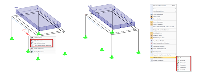
In addition to the options of Project Navigator - Display, you can modify the visibility of structures (members, surfaces, and so on) and guide objects (dimensions, comments, guidelines, and so on) in the menu and toolbar using the shortcut menus.

Using the Timber Design add-on, timber column design is possible according to the 2018 NDS standard ASD method. Accurately calculating timber member compressive capacity and adjustment factors is important for safety considerations and design. The following article will verify the maximum critical buckling strength calculated by the Timber Design add-on using step-by-step analytical equations as per the NDS 2018 standard including the compressive adjustment factors, adjusted compressive design value, and final design ratio.
.png?mw=640&hash=44d3f64925841d58547bef5a5e8ff90fab8aceaf)
The American Wood Council (AWC) has released the 2018 Edition of the National Design Specification (NDS) for Wood Construction. This is the second edition of the NDS to contain a chapter dedicated to cross-laminated timber (CLT) design. Therefore, a couple of revisions were included in the 2018 NDS when compared to the previous 2015 Edition.
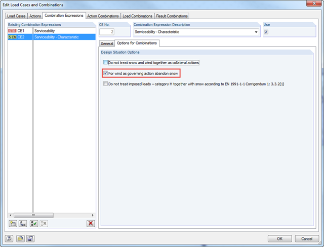
According to DIN EN 1990/NA:2010‑12 - NDP to A.1.2.1(1) Comment 2, it is possible to neglect the combination of snow as a collateral action in cases of wind/snow combination with wind as the leading action in wind zones III and IV.

In addition to the basic combination rules of EN 1990, there are other combination conditions for actions on road bridges specified in EN 1991‑2 that must be taken into account. RFEM and RSTAB provide automatic combinatorics that can be activated in the General Data when selecting the standard EN 1990 + EN 1991‑2. The partial safety factors and combination coefficients depending on the action category are preset when selecting the respective National Annex.

Silos are used as large containers for storage of bulk materials such as agricultural products or source materials as well as intermediates of industrial production. The structural engineering of such structures requires a precise knowledge of the stresses due to particulate solids in the building structure. The standard EN 1991‑4 "Actions on Silos and Tanks" [1] provides the general principles and requirements for determining these actions.
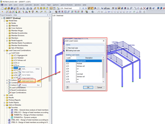
If you want to import a block with previously saved loads into an existing model, the load cases are not integrated into the existing load cases, but are added to the existing ones.
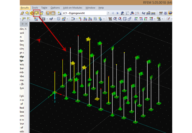
You can select an object in RFEM or RSTAB by simply clicking it. However, only the last object clicked will stay selected. In order to select several objects at a time, press the Control key while clicking. Since this procedure is not always possible, you can use the "Add to Selection" function in the toolbar or in the "Edit" → "Select" menu.
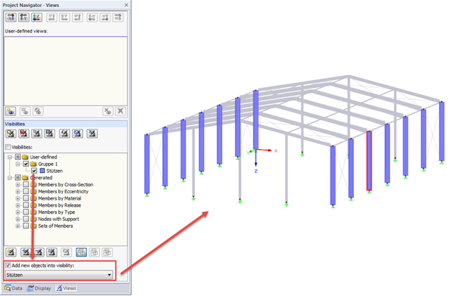
If new objects are created in an existing visibility, they are hidden immediately, since they do not comply with the particular visibility. However, if you want to display the new objects immediately in an existing visibility, for example when creating a new member, simply select the "Add new objects to visibility" check box.
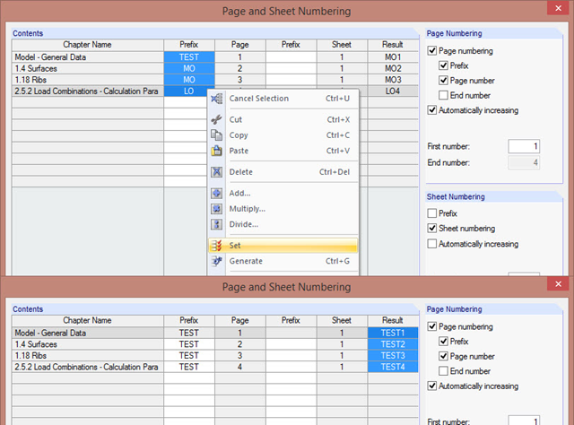
The "Page and Sheet Numbering" dialog box allows you to add a prefix to page and sheet numbering. It can be an abbreviation that specifies by chapter all model data in the numbering (for example, with "MO").

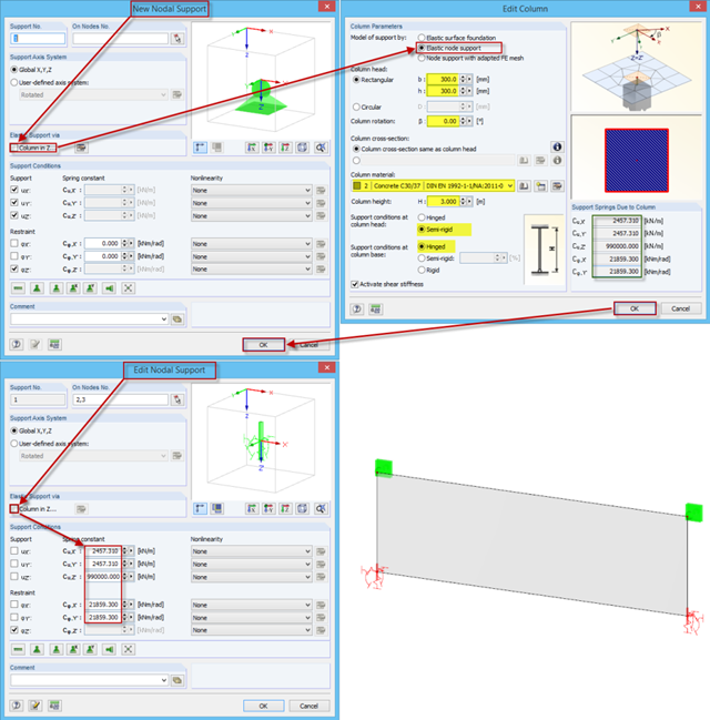
For line supports, there is an option to graphically display the additional information for all directions.

In RF‑/FOUNDATION Pro, the available reinforcing steel diameters can be adjusted by the user. The adjustment of the available rebar diameters works similarly to the same function in the RF‑/CONCRETE (Members) and RF‑/CONCRETE Columns add‑on modules.
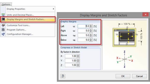
Sometimes, a model in the graphic window is displayed without filling the entire window, or with overly large margins after clicking the [Show Whole Model] button. To set the size of the graphic margins, click "Options" → "Display Margins and Stretch Factors". The value specifies the percentage of the margin relative to the graphic window size.
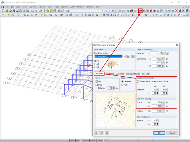
The length of the guidelines corresponds to the dimensions of the set grid and can be adapted by setting the grid.
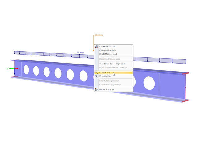
The display size of the load vectors can be adjusted quickly in the load shortcut menu: Right-click the load icon and select "Increase Display Size" or "Reduce Display Size" from the menu.
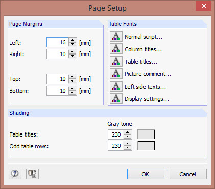
The layout of a printout report can be adjusted by changing fonts, font colors, page margins, and table shading.

It is possible to edit a reinforcement layout or an existing reinforcement directly in the reinforcement's 3D rendering.

In RF‑/FOUNDATION Pro, reinforcement drawings are displayed after designing the foundation, where you can record all necessary structures of the reinforcement steel.

For relatively large or relatively small surfaces, it can happen that the automatically created result values do not fit the model: In the case of large surfaces, there can be too many result values; in the case of small surfaces, too few.